Loading...

Brake Calculation
Choice of brake

The choice of brake in terms of braking torque required \( M_{f}\left [ Nm \right ] \) for a given application is subject to knowledge of the design data.

These data are as follows:

  • Total total total inertia Total total inertia \( I_{tot}\left [ kg\cdot m^{2} \right ] \) rotating parts reduced to the crankshaft.
  • The maximum engine speed \( n_{0}\left [ \frac{giri}{min} \right ] \).
  • The maximum permissible braking time \( t_{f}\left [ sec \right ] \).
  • The couple acting on the system \( M_{l}\left [ Nm \right ] \) which can be represented, for example, by a load to be lifted or by a moment of strength.
  • The operating frequency of the brake, i.e. the number of manoeuvres performed by the brake in one hour \( m\left [ \frac{1}{h} \right ] \).

In addition to these, other data, such as the average ambient temperature, specific environmental conditions (e.g. humidity, dust, etc.) and the mounting position of the motor, are useful for determining the most efficient way of operating the brake.

Attention, please:
If a brake unit with a special friction material is required to avoid the "sticking" effect, the nominal torque declared for the individual brake is only reached after the surfaces of the friction material have been properly run in.

Functional limitations: all the devices produced by Temporiti S.r.L. may have serious functional limitations, in the event that the ambient temperature, the humidity value, the environmental salt concentrations exceed those of the "Standard Temperature and Pressure (STP)"; or there is the presence of dust, acids, oil, both in liquid and gaseous form.
For these circumstances it is absolutely necessary to contact our technical offices to find the functional solution of the case, and prepare a mandatory maintenance plan every 3 months, subject to the limitations of work mentioned above.

The braking torque value in Nm at the start of operation is approximately 40% lower than the stated nominal value.

Selection criteria

Four more frequent cases have been identified and standardised for the definition of the braking torque in order to exemplify and simplify the calculation:

In the formulas shown, some quantities are used to verify the application, in accordance with the tables and graphs on the pages of the catalogue. These quantities are:

\( C_{s}\geqslant 2 \) safety factor;
\( C_{t}\cong 0.995 \) coefficient of reduction of intervention time;
\( L \) maneuvering [J] which must be dissipated in heat by the brake;
\( W \) rated motor power [W].
Before making the electrical connection Check that there is grounding
Approximate evaluation of the braking torque

Knowing only the power \( W \)of the engine and its maximum number of revolutions \( n_{0} \), the necessary braking torque \( M_f \) can be calculated in an approximate manner using the following formula:

\( M_{f}=\frac{W}{\left ( \frac{2\pi \cdot n_{0}}{60} \right )}\cdot C_{S} \)

If it is not possible to control the heat dissipation, the safety coefficient \( C_S \) must be selected according to the required application.

Determine the agent pair on the system \( M_L \) and define the application of the load. From the paragraph "Selection criteria" determine the type of cargo.
The four types presented satisfy the majority of braking cases.
Then choose the formula needed to meet the needs of the load.

From formula 1, \( M_L \) subtracts energy through the load and therefore the value of \( M_L \) can be lower.

Thermal dissipation verification

During braking, a certain amount of heat develops which must be dissipated by the brake.

It is therefore necessary to check that this amount of heat is compatible with the number of operations per hour that the brake must perform.

Formula 4
(Case A)

\( L=\frac{I_{TOT}\cdot\left ( \frac{2\pi n_{0}}{60} \right )^{2}}{2} \) \( \cdot \) \( \left ( \frac{M_{f}}{M_{f}-M_{L}} \right ) \)

Formula 5
(Case B)

\( L=\frac{I_{TOT}\cdot\left ( \frac{2\pi n_{0}}{60} \right )^{2}}{2} \) \( \cdot \) \( \left ( \frac{M_{f}}{M_{f}-M_{L}} \right ) \)

Formula 6
(Case C/D)

\( L=\frac{I_{TOT}\cdot\left ( \frac{2\pi n_{0}}{60} \right )^{2}}{2} \)

Knowing the number of manoeuvres/hour to be executed, enter the "Chart 1" and check that point K is below the limit curve of the selected brake type.

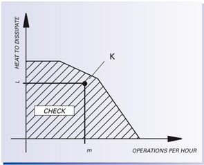
If this is not the case, switch to a higher "dash" and repeat the operation.

Air-gap adjustment with 0.1mm wear

The maximum number of manoeuvres \( m_{max} \) possible before recording the air gap is obtained with "Chart 2".

Entering the abscissae axis with work \( L \) to dissipate and read on the yards of the selected brake curve the number of total manoeuvres. In terms of time (hours), the adjustment is obtained with the following formula:

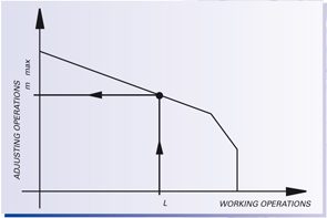
\( H_{reg}=\frac{m_{max}}{m}\)

The above formula allows the calculation of the consumption equal to 0.1mm air gap. The functionality of the brake is guaranteed for a maximum air gap value of 0.7mm (consumption 0.5mm).